概要
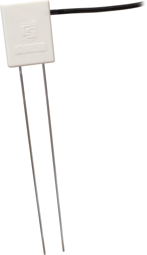
The CS650-LC is a multiparameter smart sensor that uses innovative techniques to monitor soil volumetric-water content, bulk electrical conductivity, and temperature. This sensor is used with the ET107 Weather Station.
Note: The cable connector for this sensor is suitable for use with an ET107 station. For other cable termination options, use the CS650 sensor instead.
続きを読むイメージ

詳細
The CS650-LC consists of two 30-cm-long stainless steel rods connected to a printed circuit board. The circuit board is encapsulated in epoxy and a shielded cable is attached to the circuit board for data logger connection.
The CS650-LC measures propagation time, signal attenuation, and temperature. Dielectric permittivity, volumetric water content, and bulk electrical conductivity are then derived from these raw values.
Measured signal attenuation is used to correct for the loss effect on reflection detection and thus propagation time measurement. This loss-effect correction allows accurate water content measurements in soils with bulk EC ≤3 dS m-1 without performing a soil specific calibration.
Soil bulk electrical conductivity is also calculated from the attenuation measurement. A thermistor in thermal contact with a probe rod near the epoxy surface measures temperature. Horizontal installation of the sensor provides accurate soil temperature measurement at the same depth as the water content. Temperature measurement in other orientations will be that of the region near the rod entrance into the epoxy body.
仕様
| Sensing Volume | 7800 cm3 (~7.5 cm radius around each probe rod and 4.5 cm beyond the end of the rods) |
| Electromagnetic |
CE compliant Meets EN61326 requirements for protection against electrostatic discharge and surge. |
| Operational Temperature | -10° to +70°C |
| Sensor Output | SDI-12; serial RS-232 |
| Measurement Time | 3 ms to measure; 600 ms to complete SDI-12 command |
| Power Supply Requirements | 6 to 18 Vdc (Must be able to supply 45 mA @ 12 Vdc.) |
| Maximum Cable Length | 610 m (2000 ft) combined length for up to 10 sensors connected to the same data logger control port |
| Rod Spacing | 32 mm (1.3 in.) |
| Ingress Protection Rating | IP68 |
| Rod Diameter | 3.2 mm (0.13 in.) |
| Rod Length | 300 mm (11.8 in.) |
| Probe Head Dimensions | 85 x 63 x 18 mm (3.3 x 2.5 x 0.7 in.) |
| Cable Weight | 35 g per m (0.38 oz per ft) |
| Probe Weight | 280 g (9.9 oz) without cable |
Current Drain |
|
| Active (3 ms) |
|
| Quiescent | 135 µA typical (@ 12 Vdc) |
Electrical Conductivity |
|
| Range for Solution EC | 0 to 3 dS/m |
| Range for Bulk EC | 0 to 3 dS/m |
| Accuracy | ±(5% of reading + 0.05 dS/m) |
| Precision | 0.5% of BEC |
Relative Dielectric Permittivity |
|
| Range | 1 to 81 |
| Accuracy |
|
| Precision | < 0.02 |
Volumetric Water Content |
|
| -NOTE- | Using Topp Equation (m3/m3) |
| Range | 5% to 50% |
| Accuracy | ±3% VWC (typical in mineral soils, where solution EC ≤ 3 dS/m) |
| Precision | < 0.05% |
Soil Temperature |
|
| Range | -10° to +70°C |
| Accuracy | ±0.5°C (for probe body buried in soil) |
| Precision | ±0.02°C |
互換性
注意: 以下は代表的な互換性情報を示しています。互換性のある製品や互換性のない製品をすべて網羅したリストではありません。
互換性に関する追加情報
RF Considerations
External RF Sources
External RF sources can affect the probe’s operation. Therefore, the probe should be located away from significant sources of RF such as ac power lines and motors.
Interprobe Interference
Multiple CS650-LC probes can be installed within 4 inches of each other when using the standard data logger SDI-12 “M” command. The SDI-12 “M” command allows only one probe to be enabled at a time.
Installation Tools
14384 Pilot Tool
The 14384 Pilot Tool has rods with similar diameters and the same spacing as the probe. The tool can be driven into the soil using force levels that might damage the probe. After removing the 14384, the probe is inserted into the established holes.
14383 Installation Tool
The 14383 Installation Tool can be used to help maintain the proper spacing and parallel orientation of rods during insertion. Use of the 14383 may reduce measurement errors by minimizing soil disturbance.
ダウンロード
CS650 / CS655 Firmware v.2 (429 KB) 02-12-2015
Current CS650 and CS655 firmware.
Note: The Device Configuration Utility and A200 Sensor-to-PC Interface are required to upload the included firmware to the sensor.
よくある質問
CS650-LCに関するよくある質問の数: 3
すべて展開すべて折りたたむ
-
すべてのセンサに異なるケーブル終端オプションがあるわけではありません。特定のセンサで利用可能なオプションは、センサ製品ページの注文情報エリアの 2 つの場所で確認できます。
モデル番号
ケーブル終端オプション リスト
センサが –ET、–ETM、–LC、–LQ、または –QD バージョンで提供されている場合、そのオプションが利用可能かどうかはセンサモデル番号に反映されます。たとえば、034B は 034B-ET、034B-ETM、034B-LC、034B-LQ、および 034B-QD として提供されています。その他のすべてのケーブル終端オプション (利用可能な場合) は、センサ製品ページの注文情報エリアの「ケーブル終端オプション」の下にリストされています。たとえば、034B-L 風力発電セットは、034B-L 製品ページの注文情報エリアに示されているように、–CWS、–PT、および –PW オプションで提供されています。
注意: 新しい製品が在庫に追加されると、通常は複数のモデル番号を作成するのではなく、1 つのセンサモデルの下に複数のケーブル終端オプションをリストします。たとえば、HC2S3-L には、HC2S3-LC モデルではなく、CS110 に接続するための –C ケーブル終端オプションがあります。
-
Campbell Scientific のセンサのほとんどは、ユーザー指定のケーブル長を示す –L として提供されています。センサが –LX モデル (「X」は他の文字) としてリストされている場合、そのセンサのケーブルの長さはユーザー指定ですが、固有のシステム用の特定のコネクタで終端されます。
- -LC モデルには、ET107、CS110、または廃止された Metdata1 に接続するためのユーザー指定のケーブル長があります。
- -LQ モデルには、RAWS-P 気象ステーションに接続するためのユーザー指定のケーブル長さがあります。
センサのメイン モデル番号の後に –L または –LX の指定がない場合、センサのケーブル長は設定されています。ケーブル長は、製品の注文情報の説明フィールドの末尾に記載されています。たとえば、034B-ET モデルの説明は、「ET ステーション用 Met One Wind セット、67 インチ ケーブル」です。ケーブル長が設定されている製品は、デフォルトでバラ線で終端されます。
ケーブルが特定のシステム用の特別なコネクタで終端されている場合、モデル番号の末尾でそのシステムを指定します。たとえば、034B-ET モデルは、ET107 システムのセンサを 034B として指定します。
- –ET モデルは、ET107 気象ステーション用のコネクタです。
- –ETM モデルは ET107 気象ステーション用のコネクタですが、交換部品を購入するときに便利な特別なシステム マウントも含まれています。
- –QD モデルは、RAWS-F クイック展開ステーション用のコネクタです。
- –PW モデルは、PWENC または配線済みシステム用のコネクタです。
-
多くの Campbell Scientific センサは、さまざまなケーブル終端オプションで利用できます。これらのオプションには次のものがあります。
- –PT (–PT w/Tinned Wires) オプションはデフォルトのオプションであり、他のオプションのように製品ラインには表示されません。ケーブルは、データロガーに直接接続するバラ線で終端します。
- –C (–C w/ET/CS110 コネクタ) オプションでは、ケーブルは CS110 電界メータまたは ET シリーズ気象ステーションに接続するコネクタで終端します。
- –CWS (–CWS w/CWS900 コネクタ) オプションでは、ケーブルは CWS900 シリーズ インターフェイスに接続するコネクタで終端します。CWS900 シリーズ インターフェイスに接続すると、センサをワイヤレス センサー ネットワークで使用できるようになります。
- –PW (–PW w/Pre-Wire Connector) オプションでは、ケーブルは事前に配線されたエンクロージャに接続されるコネクタで終端します。
- –RQ (–RQ w/RAWS コネクタ) オプションでは、ケーブルは RAWS-P 常設リモート自動気象ステーションに接続するコネクタで終端します。
注意: ケーブル終端オプションの選択肢はセンサによって異なります。たとえば、センサには選択可能なオプションがまったくないか、複数ある場合があります。特定のセンサに必要なオプションがリストされていない場合は、Campbell Scientific に問い合わせてサポートを受けてください。
以下に記載
Privacy Policy Update
We've updated our privacy policy. 詳細はこちら
Cookie Consent
Update your cookie preferences. クッキーの設定を更新する


