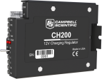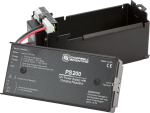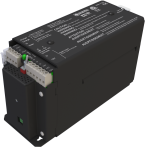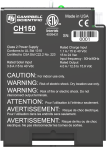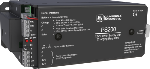
電圧とアンペア数を管理してバッテリを保護


利点と特徴
- 電源への高アンペア、高電圧のダメージから保護
- 負荷とバッテリ電流の両方をモニタ可能
- バッテリ逆接転保護
- 充電入力電圧、バッテリの電圧、オンボードの温度、バッテリの電流、負荷電流をリアルタイムで測定
- 2段階の定電圧充電と温度補正により、バッテリ充電を最適化し、バッテリ寿命を延長
- 2つの充電ソース(ソーラーパネル、ACウォールチャージャーなど)の同時接続が可能
イメージ


CAD ファイル:
詳細
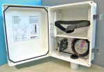
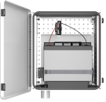
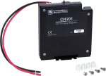
PS200電源は、充電式、7 Ahバルブ制御鉛蓄電池(VRLA)と充電レギュレータで構成されています。 このマイクロコントローラベースのスマート・チャージャーは、バッテリの充電を最適化し、バッテリの寿命を延ばす2段階の定電圧充電と温度補償を備えています。 2つの入力端子により、2つの充電ソースを同時に接続できます。 PS200はまた、利用可能なソーラー充電リソースを最大化するソーラー入力用の最大電力点追跡アルゴリズムを組み込んでいます。 RS-232およびSDI-12端子により、PS200は充電パラメータをデータロガーに転送できます。
仕様
| 動作温度 | -40° ~ +60°C (VRLA バッテリの製造元は、「熱はバッテリを破壊する」と述べており、バッテリを 50°C 以下で動作させることを推奨しています。) |
| 寸法 | 19 x 7.6 x 10.6 cm (7.5 x 3 x 4.2 in.) |
CHARGE - CHARGE 端子 (AC または DC 電源) |
|
| AC | 18 ~ 24 VRMS (最大 1.2 ARMS) |
| DC | 16 ~ 40 Vdc (最大 1.1 Adc) |
SOLAR 端子 (ソーラーパネルまたはその他の DC 電源) |
|
| -注意- | バッテリ電圧が 8.7 V 未満の場合、フォールドバック電流制限により、電流制限が 3.0 A 未満になることがあります。 |
| 入力電圧範囲 | 15 ~ 40 Vdc |
| 最大充電電流 | 4.0 Adc (標準) (充電器によって3.2~4.9 ADC) |
静止電流 |
|
| 充電源なし | 300 μA (最大) |
| バッテリ未接続 | 2 mA (最大) |
バッテリ充電 |
|
| -注意- | バルブ制御鉛蓄電池用の 2 段階温度補償定電圧充電。サイクルおよびフロート充電電圧パラメータは、記載されているデフォルト値を使用してプログラム可能です。 |
| サイクル充電 | Vbatt(T) = 14.70 V - (24 mV) x (T-25°C) |
| フロート充電 | Vbatt(T) = 13.65 V - (18 mV) x (T-25°C) |
| 正確度 | ±1% (充電電圧が-40°~+60°Cを超える場合) |
電源出力(+12端子) |
|
| 電圧 | バッテリからの非調整 12 V |
| 4 A 自己リセット可能サーマル ヒューズ ホールド電流制限 |
|
測定 |
|
| -注意- | -40° ~ +60°C の場合 |
| 平均バッテリ電圧 | ±(読み取り値の 1% + 15 mV) |
| 平均バッテリ/負荷電流レギュレータ入力電圧 |
±(読み取り値の 2% + 2 mA) 電流のインパルス型変化では、平均電流誤差が ±(読み取り値の 10% + 2 mA) になる場合があります。 |
| ソーラー |
±(読み取り値の 1% - 0.25 V) / -(読み取り値の 1% + 1 V) 入力の逆流防止ダイオードにより、1.0 V の負のオフセットが最悪のケースになります。通常のダイオード降下は 0.35 V です。 |
| 連続 |
±(読み取り値の 1% - 0.5 V) / -(読み取り値の 1% + 2 V) AC フルブリッジの 2 つの直列ダイオードにより、2.0 V の負のオフセットが最悪のケースになります。通常のダイオード降下はそれぞれ 0.35 で、合計 0.7 V です。 |
| 充電器温度 | ± 2°C |
ダウンロード
PS200 Example Programs v.1.1 (36.4 KB) 08-12-2014
CR1000 programming examples for use with the PS200. The examples show how to use both SDI-12 and RS-232 advanced instruction programming techniques.
CH200 / PS200 OS v.11 (434 KB) 24-04-2020
Execution of this download installs the CH200 / PS200 Operating System on your computer.
Note: The Device Configuration Utility is used to upload the included operating system to the CH200 / PS200.
よくある質問
PS200に関するよくある質問の数: 8
すべて展開すべて折りたたむ
-
バッテリ製造元は、バッテリを少なくとも 3 ~ 6 か月に 1 回充電することを推奨しています。29796 などの追加の壁掛け充電器を利用できる場合は、Campbell Scientific では、常に AC 電源に接続しておくことを推奨しています。
-
はい。PS100 または PS200 を備えた適切に設計されたシステムでは、短時間の停電時に CR1000 を継続的に動作させることができます。ただし、システムの総消費電流によって駆動時間が異なるため、どの程度の停電時間に耐えられるかを判断するために負荷分析を実行することを推奨しています。
-
PS100 はフロート専用充電器で、20 W のソーラーパネルと最大負荷約 1 A に制限されています。
より高度な PS200 は、温度に応じて最大約 4 A を負荷に供給しながら、より高いレートで充電し、より大きなソーラーパネル (90 W) を使用できる多段コントローラです。PS200 は、MPPT (最大電力点追従) 技術を組み込んだスマート充電器で、データロガーで調べて、その状態、ソーラーパネルの状態、負荷電流、バッテリ電圧、および正味バッテリ電流を確認できます。この点で、PS200 はハイテクセンサとしてだけでなく、充電レギュレータとしても機能します。
PS100 には温度補正用の温度センサがあります。PS200 には同様のオンボード温度センサがありますが、より効率的で、同様の負荷でそれほど多くの熱を放散しません。 PS200 には、オンボードの温度センサを使用するのではなく、独立したバッテリ温度測定値を充電器に送信できる機能もあります。
-
CH200 または PS200 は、その時点で最も電圧が高い電源からのみ電力を引き出します。たとえば、レギュレータは、日中でも 18 V 50 W ソーラーパネルからではなく、24 Vdc 壁面トランスから 20 W の入力を取ります。停電すると、50 W ソーラーパネルは日中に充電され、夜間は充電されません。
-
バッテリ上部の刻印を探します。刻印は YYMMDDXX の日付形式になっている場合があります。
- YY は年です。
- MM は月です。
- DD は日です。
- XX は製造工場です。
これはバッテリの寿命を示します。
-
PS100、PS150、PS200 モデルは、壁の変圧器またはソーラー パネルから AC または DC 電源を取り込みます。内部レギュレータは、バッテリが過充電にならないように (温度に基づいて) バッテリへの充電を制御します。
スイッチがオンの場合、バッテリからの電圧は、調整されたバッテリから負荷に流れ戻されます。ただし、そのバッテリの電圧は、11.9 V、13.2 V、またはバッテリがたまたま持っている他の値である可能性があります。電圧が常に正確に 12.0 Vdc であるとは限らないことを理解することが重要です。むしろ、バッテリが再充電されたり消耗したりすると、電圧は上下します。
-
ソーラーパネルからの電圧は、一日を通して変動します。
AC 電源を使用している場合、電圧は通常安定しています。
レギュレータ入力に入力される電圧は、バッテリが過充電されないように (電解質が沸騰して壊れないように) 制御されます。レギュレータに接続されたバッテリが良好な場合、極寒のときに表示される最高電圧は 14 Vdc をわずかに上回る程度ですが、通常は 13.2 Vdc 程度です。
バッテリがほぼ消耗している場合 (電圧計で確認)、またはセルがショートしているバッテリの場合、バッテリ電圧が非常に低くなります。データロガーデータに表示される最低電圧は通常約 10.0 V です。これは、データロガーがそのレベル付近でシャットダウンし、電圧が 11 ボルトまたは 12 ボルトのレベルに上昇するのを待つためです。
バッテリに流入するリップル電圧は数ミリボルトですが、バッテリはそのノイズのほとんどを除去し、かなり安定した電圧を提供します。
-
はい。充電レギュレータの G および 12V 端子は、データロガーに電力を供給する緑色のコネクタに接続する黒色および赤色のワイヤを接続するために使用されます。
Privacy Policy Update
We've updated our privacy policy. 詳細はこちら
Cookie Consent
Update your cookie preferences. クッキーの設定を更新する
