メンテナンスフリー


概要
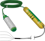
229は-10~-2500kPaの土壌水ポテンシャルを測定するセンサです。CE4またはCE8電流励磁モジュールに接続する必要があります。Campbell Scientificのデータロガーが電流励磁モジュールを制御、センサで測定し、土壌の水分マトリックポテンシャルを計算します。
続きを読む利点と特徴
- ほとんどのCampbell Scientificデータロガーとの互換性
- 広範囲のマトリックポテンシャルを測定
- 土壌中の塩分の影響を受けない測定値
- メンテナンス不要で長寿命
- AM16/32シリーズマルチプレクサと互換性があり、複数のセンサの測定が可能
イメージ


詳細
-
CR6、CR800、CR850、CR1000、CR3000、CR5000の配線パネルに組み込まれたサーミスタ
- CR9000X測定制御システム用のCR9050またはCR9051E入力モジュールの配線パネルに組み込まれたPRT
仕様
| 動作温度範囲 | -5° ~ +30°C |
| 通常環境温度範囲 | -40° ~ +70°C |
| 測定範囲 | -10 ~ -2500 kPa |
| 測定時間 | 30 秒 (通常) |
| 熱電対タイプ | 銅/コンスタンタン (タイプ T) |
| ヒーター抵抗 | ~34 Ω |
| 分解能 | ~1 kPa (マトリックポテンシャル < -100 kPa) |
| 直径 | 1.5 cm (0.6 in.) |
| 長さ | 6.0 cm (2.4 in.) |
| ケーブル重量 | ~23 g/m (0.25 oz/ft) |
| センサー重量 | 10 g (0.35 oz) |
互換性
注意: 以下は代表的な互換性情報を示しています。互換性のある製品や互換性のない製品をすべて網羅したリストではありません。
Data Loggers
| 製品 | 互換性 | 注意 |
|---|---|---|
| CR1000 (リタイア) | ||
| CR1000X (リタイア) | ||
| CR300 (リタイア) | ||
| CR3000 (リタイア) | ||
| CR310 | ||
| CR350 | ||
| CR6 | ||
| CR800 (リタイア) | ||
| CR850 (リタイア) |
互換性に関する追加情報
電流励磁モジュール
229の発熱体に定電流を供給するには、CE4またはCE8のいずれかの電流励磁モジュールが必要です。CE4とCE8の違いは、電流を供給する229センサの数だけです。CE4は最大4個の229に電流を供給し、CE8は最大8個の229に電流を供給します。どちらのモジュールも12 Vdc電源を必要とします。
マルチプレクサ
より多くのセンサを必要とするアプリケーションでは、CE4またはCE8の出力を、出力の数だけAM16/32シリーズのマルチプレクサに接続することができ、システム容量を大幅に拡張できます。マルチプレクサを使用する場合は、30mAを超えるスイッチング電流がメカニカルリレーの接触面を劣化させることに注意する必要があります。したがって、データロガーは、マルチプレクサーのリレーを保護するために、マルチプレクサーのチャンネルを切り替える前に電流励起モジュールをオフにするようにプログラムする必要があります。
データロガーに関する確認
プローブ 1 つにつき、差動チャンネル 1 つと電流励起チャンネル 1 つが必要です。各 CE4 または CE8 電流励磁モジュールには、1 つのデータロガーCポートが必要です。
プログラミング
229は、データロガー命令のシーケンスによって測定されます。このシーケンスでは、50 mA の電流が加熱要素に印加されている間に、熱電対が 0 秒、1 秒、30 秒で測定されます。この電流は、CE4 または CE8 電流励起モジュールによって供給されます。加熱中の温度上昇は、土壌水分マトリック ポテンシャルに関係しています。
基準温度の測定
-
CR800、CR850、CR1000、CR3000、CR5000の配線パネルに組み込まれたサーミスタ
-
CR9050 または CR5000 の配線パネルに組み込まれた PRT
-
CR9000X測定制御データロガー用CR9051E入力モジュール
-
CR7測定制御データロガー用CR723T入力カードの配線パネルに組み込まれたPRT
- CR10Xの配線パネルに接続するCR10XTCRサーミスタ
よくある質問
229-Lに関するよくある質問の数: 11
すべて展開すべて折りたたむ
-
はい。Campbell Scientific では、ヒーターをオンにする前にセンサの温度を測定して記録することを推奨しています。その測定値は土壌温度の測定値として使用できます。マトリック ポテンシャルの測定が 15 分ごとに 1 回以上行われない限り、センサに大きな熱が蓄積されることはなく、センサ温度は土壌温度と同じになります。
-
dT の値が非常に低い場合、特に負の値は、229-L センサが測定時間中に加熱されていないことを示します。最も考えられる原因は、ヒーター ワイヤの損傷、1 本以上のワイヤの緩み、または定電流励起モジュールの故障です。
最初に確認すべきは、ヒーター ワイヤ自体です。抵抗計を使用して、229-L の黒と緑のワイヤ間の抵抗を測定します。抵抗は約 33 ~ 36 オームになるはずです。スケール外または無限大の読み取り値は、ヒーター ワイヤの断線を示しています。読み取り値が低い場合は、ヒーター ワイヤのショートを示している可能性があります。どちらの場合も、修正するには、センサ ワイヤを掘り出して損傷がないか調べる必要があります。
次のチェックでは、以下の場所で電気接続が良好であることを確認します。
- 黒と緑のセンサ線が定電流インターフェースまたはマルチプレクサに接続される場所
- マルチプレクサの共通線が定電流インターフェースに接続される場所
- 定電流インターフェースがデータロガーの 12V、G、およびCポートに接続される場所
これらのワイヤのそれぞれには、約 1/4 インチの裸銅が端子にしっかりと接続されている必要があります。
最後に、CE4 または CE8 定電流モジュールをマルチメーターでチェックして、50 mA を出力していることを確認します。12V とアース端子ネジ間の電圧を測定して、定電流モジュールがデータロガーから電力を受け取っていることを確認します。次に、データロガーCポートと CTRL チャネルを接続するワイヤを一時的にデータロガーの 5 V チャネルに移動し、モジュールが常にオンになるようにして、電流出力を測定できるようにします。マルチメータをミリアンペア測定に設定し、電流を測定します。50 mA ± 1 mA である必要があります。電流出力がその範囲外の場合は、定電流モジュールを修理または交換する必要があります。
-
詳細とサンプルプログラムについては、29-L マニュアルal.の「Example Programs」セクションを参照してください。
-
加熱要素はエバノーム ワイヤで作られています。この要素はステンレス製の注射針の中にエポキシで覆われており、腐食環境にさらされることはありません。したがって、センサのこの部分は 5 年間は故障しないはずです。ただし、センサ ケーブルとセラミック マトリックスは、腐食環境に 5 年間さらされると損傷を受ける可能性があります。
-
現時点では、Campbell Scientific は 229-L の校正サービスを提供していません。このサービスを提供する会社があります。詳細については、Campbell Scientific にお問い合わせください。
-
すべてのセンサに異なるケーブル終端オプションがあるわけではありません。特定のセンサで利用可能なオプションは、センサ製品ページの注文情報エリアの 2 つの場所で確認できます。
モデル番号
ケーブル終端オプション リスト
センサが –ET、–ETM、–LC、–LQ、または –QD バージョンで提供されている場合、そのオプションが利用可能かどうかはセンサモデル番号に反映されます。たとえば、034B は 034B-ET、034B-ETM、034B-LC、034B-LQ、および 034B-QD として提供されています。その他のすべてのケーブル終端オプション (利用可能な場合) は、センサ製品ページの注文情報エリアの「ケーブル終端オプション」の下にリストされています。たとえば、034B-L 風力発電セットは、034B-L 製品ページの注文情報エリアに示されているように、–CWS、–PT、および –PW オプションで提供されています。
注意: 新しい製品が在庫に追加されると、通常は複数のモデル番号を作成するのではなく、1 つのセンサモデルの下に複数のケーブル終端オプションをリストします。たとえば、HC2S3-L には、HC2S3-LC モデルではなく、CS110 に接続するための –C ケーブル終端オプションがあります。
-
Campbell Scientific のセンサのほとんどは、ユーザー指定のケーブル長を示す –L として提供されています。センサが –LX モデル (「X」は他の文字) としてリストされている場合、そのセンサのケーブルの長さはユーザー指定ですが、固有のシステム用の特定のコネクタで終端されます。
- -LC モデルには、ET107、CS110、または廃止された Metdata1 に接続するためのユーザー指定のケーブル長があります。
- -LQ モデルには、RAWS-P 気象ステーションに接続するためのユーザー指定のケーブル長さがあります。
センサのメイン モデル番号の後に –L または –LX の指定がない場合、センサのケーブル長は設定されています。ケーブル長は、製品の注文情報の説明フィールドの末尾に記載されています。たとえば、034B-ET モデルの説明は、「ET ステーション用 Met One Wind セット、67 インチ ケーブル」です。ケーブル長が設定されている製品は、デフォルトでバラ線で終端されます。
ケーブルが特定のシステム用の特別なコネクタで終端されている場合、モデル番号の末尾でそのシステムを指定します。たとえば、034B-ET モデルは、ET107 システムのセンサを 034B として指定します。
- –ET モデルは、ET107 気象ステーション用のコネクタです。
- –ETM モデルは ET107 気象ステーション用のコネクタですが、交換部品を購入するときに便利な特別なシステム マウントも含まれています。
- –QD モデルは、RAWS-F クイック展開ステーション用のコネクタです。
- –PW モデルは、PWENC または配線済みシステム用のコネクタです。
-
多くの Campbell Scientific センサは、さまざまなケーブル終端オプションで利用できます。これらのオプションには次のものがあります。
- –PT (–PT w/Tinned Wires) オプションはデフォルトのオプションであり、他のオプションのように製品ラインには表示されません。ケーブルは、データロガーに直接接続するバラ線で終端します。
- –C (–C w/ET/CS110 コネクタ) オプションでは、ケーブルは CS110 電界メータまたは ET シリーズ気象ステーションに接続するコネクタで終端します。
- –CWS (–CWS w/CWS900 コネクタ) オプションでは、ケーブルは CWS900 シリーズ インターフェイスに接続するコネクタで終端します。CWS900 シリーズ インターフェイスに接続すると、センサをワイヤレス センサー ネットワークで使用できるようになります。
- –PW (–PW w/Pre-Wire Connector) オプションでは、ケーブルは事前に配線されたエンクロージャに接続されるコネクタで終端します。
- –RQ (–RQ w/RAWS コネクタ) オプションでは、ケーブルは RAWS-P 常設リモート自動気象ステーションに接続するコネクタで終端します。
注意: ケーブル終端オプションの選択肢はセンサによって異なります。たとえば、センサには選択可能なオプションがまったくないか、複数ある場合があります。特定のセンサに必要なオプションがリストされていない場合は、Campbell Scientific に問い合わせてサポートを受けてください。
-
詳細については、229-L マニュアルの「Calibration」セクションを参照してください。
-
ワーストケースですべての誤差を合計すると、熱電対の正確度は ±0.5°C になります。熱電対測定の詳細については、データロガーのマニュアルの「Thermocouple Measurements」セクションを参照してください。
ケーススタディ
Chevron Mining, Inc., (CMI) owned and operated a 6.6 million-metric-ton-per-year (6.6 million-U.S.-ton) molybdenum mining and......続きを読む
硬岩金属採掘に伴う酸性岩排水 (ARD) の問題は、多くの採掘作業にとって最大の環境課題の 1 つです。ARD の形成には、酸素、水、反応性岩 (鉱山の廃岩廃棄場内によく見られる) の 3 つの要素が必要です。ARD 防止戦略は数多くありますが、通常は、反応性廃岩への水と酸素の流入と反応性廃岩を通過する水と酸素の流入を最小限に抑えて、硫化物の酸化を減らすことに重点を置いています。一般的で効果的な手法は、反応性廃棄物を低浸透性のキャップと植物で覆い、反応性岩を酸素と水から隔離することです。このようなキャップの効果は、廃岩内の水の動き、酸素含有量、温度を監視することで、現場で評価できます。 モンタナ州ボーズマンの Schafer & Associates は、10......続きを読む
Privacy Policy Update
We've updated our privacy policy. 詳細はこちら
Cookie Consent
Update your cookie preferences. クッキーの設定を更新する


