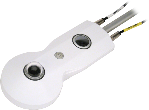
4方向、研究品質の放射計、サーミスタと Pt-100 内蔵


概要
Kipp & Zonen 製のCNR4 は Campbell Scientific データロガー向けにケーブル接続された研究グレードの放射収支計で、下向き放射と上向き放射のエネルギーバランスを測定します。当社のデータロガーは CNR4 の出力を測定します。この放射収支計は、サイエンスグレードのエネルギーバランス研究のための専門的なソリューションを提供します。
続きを読む利点と特徴
- 研究レベルのパフォーマンス
- 上部の長波検出器のレンズドームにより、水滴が簡単に転がり落ち、視野がほぼ 180° に拡大
- 内部温度センサにより、測定の温度補正が可能
- 乾燥カートリッジにより、電子機器を乾燥状態に保つ
- 結露の発生を抑え、霜を溶かすヒータ付きの CNF4 換気ユニットとの互換性
- 短波と長波の赤外放射を別々に出力することで、精度が向上し、徹底した品質保証を実現
- ソーラーシールドにより、センサへの熱の影響を軽減
イメージ


詳細
仕様
| センサ | サーモパイル日射計 2 台、日射計 2 台、Pt100 RTD、サーミスタ |
| 測定の説明 | 短波および長波の入射および出射放射を測定 |
| 応答時間 | < 18 秒 |
| 感度の温度依存性 | < 4% (-10°~+40°C) |
| 感度 | 5 ~ 20 μV W-1 m2 |
| 非直線性 | < 1% |
| 傾斜誤差 | < 1% |
| 方向誤差 |
< 20 W m-2 (日射計) 1000 W/m2のビーム放射で最大80°の角度 |
| 動作温度範囲 | -40° ~ +80°C |
| コンプライアンス | CE ガイドライン 89/336/EEC 73/23/EEC に準拠 |
| 高さ | 6.6 cm (2.6 in.) ドーム間 |
| 幅 | 11.1 cm (4.4 in.) |
| 長さ |
|
| 重量 | 850 g (30.0 oz) ケーブル除く |
日射計 |
|
| 測定範囲 |
|
| 1 日合計の不確実性 |
|
| 出力範囲 |
|
互換性
注意: 以下は代表的な互換性情報を示しています。互換性のある製品や互換性のない製品をすべて網羅したリストではありません。
Data Loggers
| 製品 | 互換性 | 注意 |
|---|---|---|
| CR1000 (リタイア) | CR1000 を使用する場合、CNR4 の内部温度は内部サーミスタで測定する必要があります。 | |
| CR3000 (リタイア) | ||
| CR6 | ||
| CR800 (リタイア) | ||
| CR850 (リタイア) |
互換性に関する追加情報
マウント
データロガーに関する考慮事項
放射成分を測定するために、4 つの差動チャネルまたは 4 つのシングルエンドチャンネルが使用されます。サーミスタを測定するには、電圧励起チャンネルと追加のシングルエンド チャンネルが必要です。 RTD を使用して温度補償測定を行う場合は、電流励起チャンネル (CR3000 および CR5000 でのみ使用可能) と差動チャンネルが必要です。
ドキュメント
マニュアル
ダウンロード
CR1000X CNR4 Program Controlling the CNF4 Heater/Ventilator v.1 (4 KB) 17-10-2019
CR1000X program measures the CNR4 and controls the CNF4 heater/ventilator based on environmental conditions, and monitors the CNF4 tachometer. The program uses an EE181 temperature and relative humidity sensor and a 03002 Wind Sentry to provide the measurements for determining when to turn the fan and heater on and off. An A21REL-12 relay switches power to the CNF4.
CR1000X CNR4 Program using Thermistor v.1 (2 KB) 17-10-2019
CR1000X program that uses differential terminals to measure the four radiation outputs and one excitation terminal and one single-ended terminal to measure the thermistor. The program measures the sensors every 1 second, performs the online processing of the data, and stores processed data to a data table called cnr4_data once every 60 minutes. It also stores the raw time-series data from CNR4 to data table called cnr4_ts.
CR3000 CNR4 Program using Pt-100 v.1 (2 KB) 17-10-2019
CR3000 program measures the Pt-100 sensor for the body temperature of the CNR4. This program requires four differential channels to measure the four radiation outputs, one current excitation channel, and one differential channel for Pt-100 measurement. It measures the sensors every 1 second, performs the online processing of the data, and stores the processed data to a data table called cnr4_data once every 60 minutes. It also stores the raw time-series data from CNR4 to data table called cnr4_ts.
よくある質問
CNR4-Lに関するよくある質問の数: 11
すべて展開すべて折りたたむ
-
はい。このセンサからの信号は、ケーブルの長さが原因で発生する損失を補うほど大きくありません。
-
2013 年 6 月現在、当社の現行および廃止された純放射線センサはすべてこのキットを使用して取り付けることができます。これには次のものが含まれます。
- 現行センサ: CNR4-L、NR-LITE2-L、NR01-L
- 販売終了センサ: CNR1、CNR1-L、CNR2-L、NR-LITE-L、Q7.1-L
-
放射計の内部 PRT を測定するには、4WPB100 が 1 台だけ必要です。
-
ネットラジオメーターは、樹木、建物、マスト、または取り付けられている構造物などの障害物によって、一日中影が落ちないように取り付けます。
Campbell Scientific は、メインの気象観測所構造から離れたオープン エリアに、別の垂直マスト上にネット ラジオメーターを設置することを推奨しています。このセンサをメインの高いタワー (30 フィート以上) に設置する必要がある場合は、センサをタワーの最上部に設置する必要があります。北半球では、センサは南を向く必要があります。南半球では、センサは北を向く必要があります。タワーで太陽光発電システム (つまり、ソーラー パネル) が使用されている場合は、ソーラー パネルがメイン タワーから離れた場所に設置されていることを確認してください。
-
CR1000 では、内部 PRT を測定するために 4WPB100 が必要です。(CR3000 や CR5000 などのデータロガーには、PRT を測定するために必要な PRT ブリッジ モジュールが組み込まれています。) CNR4-L にも内部サーミスタが含まれており、CR1000 で直接測定できることに注意してください。このため、CR1000 を使用する場合、Campbell Scientific では通常、PRT ではなく内部サーミスタを使用して CNR4-L の内部温度を監視することを推奨しています。
-
すべてのセンサに異なるケーブル終端オプションがあるわけではありません。特定のセンサで利用可能なオプションは、センサ製品ページの注文情報エリアの 2 つの場所で確認できます。
モデル番号
ケーブル終端オプション リスト
センサが –ET、–ETM、–LC、–LQ、または –QD バージョンで提供されている場合、そのオプションが利用可能かどうかはセンサモデル番号に反映されます。たとえば、034B は 034B-ET、034B-ETM、034B-LC、034B-LQ、および 034B-QD として提供されています。その他のすべてのケーブル終端オプション (利用可能な場合) は、センサ製品ページの注文情報エリアの「ケーブル終端オプション」の下にリストされています。たとえば、034B-L 風力発電セットは、034B-L 製品ページの注文情報エリアに示されているように、–CWS、–PT、および –PW オプションで提供されています。
注意: 新しい製品が在庫に追加されると、通常は複数のモデル番号を作成するのではなく、1 つのセンサモデルの下に複数のケーブル終端オプションをリストします。たとえば、HC2S3-L には、HC2S3-LC モデルではなく、CS110 に接続するための –C ケーブル終端オプションがあります。
-
Campbell Scientific のセンサのほとんどは、ユーザー指定のケーブル長を示す –L として提供されています。センサが –LX モデル (「X」は他の文字) としてリストされている場合、そのセンサのケーブルの長さはユーザー指定ですが、固有のシステム用の特定のコネクタで終端されます。
- -LC モデルには、ET107、CS110、または廃止された Metdata1 に接続するためのユーザー指定のケーブル長があります。
- -LQ モデルには、RAWS-P 気象ステーションに接続するためのユーザー指定のケーブル長さがあります。
センサのメイン モデル番号の後に –L または –LX の指定がない場合、センサのケーブル長は設定されています。ケーブル長は、製品の注文情報の説明フィールドの末尾に記載されています。たとえば、034B-ET モデルの説明は、「ET ステーション用 Met One Wind セット、67 インチ ケーブル」です。ケーブル長が設定されている製品は、デフォルトでバラ線で終端されます。
ケーブルが特定のシステム用の特別なコネクタで終端されている場合、モデル番号の末尾でそのシステムを指定します。たとえば、034B-ET モデルは、ET107 システムのセンサを 034B として指定します。
- –ET モデルは、ET107 気象ステーション用のコネクタです。
- –ETM モデルは ET107 気象ステーション用のコネクタですが、交換部品を購入するときに便利な特別なシステム マウントも含まれています。
- –QD モデルは、RAWS-F クイック展開ステーション用のコネクタです。
- –PW モデルは、PWENC または配線済みシステム用のコネクタです。
-
多くの Campbell Scientific センサは、さまざまなケーブル終端オプションで利用できます。これらのオプションには次のものがあります。
- –PT (–PT w/Tinned Wires) オプションはデフォルトのオプションであり、他のオプションのように製品ラインには表示されません。ケーブルは、データロガーに直接接続するバラ線で終端します。
- –C (–C w/ET/CS110 コネクタ) オプションでは、ケーブルは CS110 電界メータまたは ET シリーズ気象ステーションに接続するコネクタで終端します。
- –CWS (–CWS w/CWS900 コネクタ) オプションでは、ケーブルは CWS900 シリーズ インターフェイスに接続するコネクタで終端します。CWS900 シリーズ インターフェイスに接続すると、センサをワイヤレス センサー ネットワークで使用できるようになります。
- –PW (–PW w/Pre-Wire Connector) オプションでは、ケーブルは事前に配線されたエンクロージャに接続されるコネクタで終端します。
- –RQ (–RQ w/RAWS コネクタ) オプションでは、ケーブルは RAWS-P 常設リモート自動気象ステーションに接続するコネクタで終端します。
注意: ケーブル終端オプションの選択肢はセンサによって異なります。たとえば、センサには選択可能なオプションがまったくないか、複数ある場合があります。特定のセンサに必要なオプションがリストされていない場合は、Campbell Scientific に問い合わせてサポートを受けてください。
-
IR 放射の損失のため、ほぼすべてのサーモパイル計器には通常、負のオフセットがあります。このオフセットは夜間に最も目立ち、ゼロではなく小さな負の値が読み取られます。この同じオフセットは日中にも存在しますが、太陽信号が大きいため目立ちません。
もう 1 つの一般的な問題は、計器の水平調整です。サーモパイル計器の水平調整では、コサイン応答が正しくないため、直接ビーム成分にエラーが発生する可能性があります。太陽が地平線に近い場合、角度が非常に浅いため、これらのエラーはより顕著になります。
-
技術的には、アルベドは表面から反射される太陽放射の割合であるため、夜間のアルベドを定量化することはできません。
アルベドを計算する際、放射量が非常に低い場合、比率に関連する誤差がかなり大きくなることを覚えておくことが重要です。たとえば、太陽が地平線上の低い位置に落ちると、反射放射と入射放射の比率は意味をなさなくなります。
アルベドは、同時に入射する日射計と反射する日射計の測定値から計算され、平均値が保存されます。これらの日射計信号は両方とも、差動入力モードである必要があります。
- 夜間は、上部の日射計が冷たい空に面するため、ドームが冷えて測定値がマイナスになります。(たとえば、空の状態によっては、-2 ~ -7 W/m2 の測定値になる場合があります。)
- 対照的に、下側の日射計は地面に面しており、地面の方が暖かくなったり寒くなったりする可能性があります。測定値はプラスになることは少なく、-2 W/m2 になることもあります。
原理的には、2 つの負の値により夜間のアルベドは 0.5 になる可能性があります。
使用するデータロガーの入力解像度、ノイズ、オフセットにより、個々の日射計の読み取り値が正確にゼロになることはほとんどありません。使用する構成によっては、データロガーによって 2 W/m2 未満として記録された正の放射値は、実際にはゼロ未満である可能性があります。
上部日射計の読み取り値、下部日射計の読み取り値、またはその両方が 2 W/m2 未満の場合、アルベド値は「未定義」または「無効」と記述する必要があります。
もう 1 つのアプローチは、フラックス値が小さくなったときにアルベドを計算しないことです。たとえば、アルベド計算で使用される最小フラックス値のカットオフ ポイントを設定します。
太陽の位置を計算する場合、別の方法として、地平線から 1° 上などの太陽の位置計算を使用する方法があります。
ケーススタディ
このケーススタディでは、中国科学院清遠森林 CERN 研究所の不均一な地形におけるCO 2 /H 2O微量ガスフラックスを測定する理論と技術を探すためにCPEC310およびAP200システムを統合する方法について説明します。 CPEC310 (閉路渦相関システム) と AP200 (大気プロファイル システム) は、微気象センサー、硝酸塩関連の微量ガス分析装置、土壌表面 CO 2フラックス システムとともに、中国科学院清遠森林 CERN フィールド研究所における森林生態学と管理に関する研究を促進する 3 つの高さ......続きを読む
現在、アンデスの熱帯氷河は急いで後退しています。 これらの氷河は、ペルー南部の乾燥した冬と干ばつの間、恒久的な水源であると考えられています。手前にいるため、この状況は注目を集めています。 コロプナはペルー最大かつ最も高い火山で、リマの南1,000 km (620 マイル) のアレキパにあります。 最高標高は 6,400 m (21,000 フィート) で、ペルーで約 3 番目に高い地点であり、年間降水量が......続きを読む
科学者や土地利用管理者は、炭素吸収における森林地帯の重要性を長い間認識してきました。研究と国際政策は主に熱帯林と生息地に焦点が当てられてきました。熱帯林と生息地は成長が早く、頻繁な伐採の影響を受けやすいためです。しかし最近では、安定的に炭素を吸収して貯蔵できる生息地が地球全体の炭素状況の重要な部分であると認識されるようになり、寒帯地域などの冷涼な気候の景観に研究の焦点が当てられるようになりました。これらの地域では成熟した森林と気温によって分解速度が制限されるため、気候変動がこれらの景観を変える潜在的な影響により、景観をより完全に理解するための取り組みが強化されています。 アラスカ大学フェアバンクス校の研究者らは、米国地質調査所の資金援助を受け、国立科学財団の長期生態学研究ネットワークの一部であるボナンザ クリーク実験林内の 3 か所の環境モニタリング サイトに機器を設置しました。これらのサイトは、微気候の違いによって決まる陸上北方景観の重要な生息地を代表する永久凍土の劣化の年代順に位置しています。3 つのサイトには、クロトウヒ林 (クロトウヒの森がそのまま残っている安定した永久凍土の地域)、永久凍土が下にある地表の氷が溶けて樹木がかなり枯死している活発なサーモカルスト サイト、活動層の深さが深く安定した樹木のない湿原サイトが含まれます。 このプロジェクトの目標は、北極圏の気候システムにおける地表、大気、海洋間の重要なつながりとフィードバックである炭素、水、エネルギーのフラックスを年間を通じて継続的に測定することです。これまで、北極圏では環境条件が厳しく、遠隔地へのアクセスが困難なため、このような研究はほとんど行われていません。冬季に太陽光発電が限られ、風力発電が実行可能な選択肢ではない場所で継続的に監視するには、電力要件が極めて低く、リモート システム診断機能を備えた堅牢なセンサーを選択する必要があります。 Bonanza Creek サイトで、渦相関フラックス測定に Campbell Scientific の EC150......続きを読む
記事とプレスリリース
Privacy Policy Update
We've updated our privacy policy. 詳細はこちら
Cookie Consent
Update your cookie preferences. クッキーの設定を更新する


