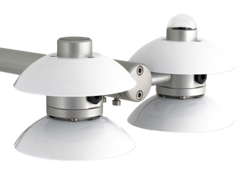
メンテナンスの手間が少ない堅牢な4成分放射収支計


概要
利点と特徴
- 内蔵の RTD により測定の温度補正が可能
- 研究レベルのパフォーマンス
- 1 W の内部ヒータにより結露の発生を抑え、霜を溶かす
- 短波と長波の赤外線を別々に出力することで、精度を高め、より徹底した品質保証を実現
- 限られたメンテナンスしか必要としない堅牢性
イメージ

詳細
仕様
| センサ | Hukseflux の SR01 ISO クラス、サーモパイル日射計、IR01 日射計、PT100 RTD |
| 測定の説明 | 短波および長波の入射および出射放射を測定 |
| 応答時間 | 18 秒 |
| 感度 | 10 ~ 40 μV W-1 m2 |
| 予想される出力範囲 | -0.1 ~ +50 mV |
| 1 日の合計の予想される精度 | ±10% |
| ヒーター | 90 Ω、1.6 W (@ 12 Vdc) |
| 動作温度範囲 | -40° ~ +80°C |
| ヒーターの電流消費量 | 約 140 mA |
| 寸法 | 26.3 x 11.3 x 12.1 cm (10.4 x 4.4 x 4.8 in.) |
| 重量 |
|
日射計 |
|
| 測定範囲 |
|
互換性
注意: 以下は代表的な互換性情報を示しています。互換性のある製品や互換性のない製品をすべて網羅したリストではありません。
Data Loggers
| 製品 | 互換性 | 注意 |
|---|---|---|
| CR1000 (リタイア) | 内部 RTD を測定するには、4WPB100 PRT ブリッジモジュールが必要です。 | |
| CR1000X (リタイア) | 内部 RTD を測定するには、4WPB100 PRT ブリッジモジュールが必要です。 | |
| CR3000 (リタイア) | ||
| CR6 | ||
| CR800 (リタイア) | ||
| CR850 (リタイア) |
Mounting Equipment
| 製品 | 互換性 | 注意 |
|---|---|---|
| 26120 |
互換性に関する追加情報
取り付け
日陰や反射を避け、空間の平均化を促進するために、NR01 は地面または作物のキャノピーから少なくとも 1.5 m の高さに設置し、測定に悪影響を与える可能性のあるすべての障害物や反射面から離してください。Campbell Scientific は、NR01 を他の取り付け構造物から少なくとも 25 フィート離れた CM300 シリーズの取り付けポールに取り付けることを推奨しています。NR01 は、CM204 または CM206 クロスアームを介して CM300 シリーズの取り付けポールに取り付けられます。
ドキュメント
カタログ
マニュアル
よくある質問
NR01-Lに関するよくある質問の数: 12
すべて展開すべて折りたたむ
-
Campbell Scientific では、センサを他の取り付け構造物から少なくとも 25 フィート離れた別の垂直パイプに取り付けることを推奨しています。
-
陰影と反射は考慮すべき重要な側面です。センサは上空の半球をはっきりと見渡せる必要があります。陰影の影響を避け、空間の平均化を促進するために、センサは地表から少なくとも 1.5 m の高さに設置する必要があります。
-
古いバージョンの Short Cut が使用されている可能性があります。最新バージョンの Short Cut をダウンロードしてください。
プログラミングのサポートについては、NR01-L の取扱説明書を参照してください。追加のサポートについては、Campbell Scientific にお問い合わせください。
-
2013 年 6 月現在、当社の現行および廃止された純放射線センサはすべてこのキットを使用して取り付けることができます。これには次のものが含まれます。
- 現行センサ: CNR4-L、NR-LITE2-L、NR01-L
- 販売終了センサ: CNR1、CNR1-L、CNR2-L、NR-LITE-L、Q7.1-L
-
放射計の内部 PRT を測定するには、4WPB100 が 1 台だけ必要です。
-
ネットラジオメーターは、樹木、建物、マスト、または取り付けられている構造物などの障害物によって、一日中影が落ちないように取り付けます。
Campbell Scientific は、メインの気象観測所構造から離れたオープン エリアに、別の垂直マスト上にネット ラジオメーターを設置することを推奨しています。このセンサをメインの高いタワー (30 フィート以上) に設置する必要がある場合は、センサをタワーの最上部に設置する必要があります。北半球では、センサは南を向く必要があります。南半球では、センサは北を向く必要があります。タワーで太陽光発電システム (つまり、ソーラー パネル) が使用されている場合は、ソーラー パネルがメイン タワーから離れた場所に設置されていることを確認してください。
-
CR1000 では、内部 PRT を測定するために 4WPB100 が必要です。(CR3000 や CR5000 などのデータロガーには、PRT を測定するために必要な PRT ブリッジ モジュールが組み込まれています。) CNR4-L にも内部サーミスタが含まれており、CR1000 で直接測定できることに注意してください。このため、CR1000 を使用する場合、Campbell Scientific では通常、PRT ではなく内部サーミスタを使用して CNR4-L の内部温度を監視することを推奨しています。
-
すべてのセンサに異なるケーブル終端オプションがあるわけではありません。特定のセンサで利用可能なオプションは、センサ製品ページの注文情報エリアの 2 つの場所で確認できます。
モデル番号
ケーブル終端オプション リスト
センサが –ET、–ETM、–LC、–LQ、または –QD バージョンで提供されている場合、そのオプションが利用可能かどうかはセンサモデル番号に反映されます。たとえば、034B は 034B-ET、034B-ETM、034B-LC、034B-LQ、および 034B-QD として提供されています。その他のすべてのケーブル終端オプション (利用可能な場合) は、センサ製品ページの注文情報エリアの「ケーブル終端オプション」の下にリストされています。たとえば、034B-L 風力発電セットは、034B-L 製品ページの注文情報エリアに示されているように、–CWS、–PT、および –PW オプションで提供されています。
注意: 新しい製品が在庫に追加されると、通常は複数のモデル番号を作成するのではなく、1 つのセンサモデルの下に複数のケーブル終端オプションをリストします。たとえば、HC2S3-L には、HC2S3-LC モデルではなく、CS110 に接続するための –C ケーブル終端オプションがあります。
-
Campbell Scientific のセンサのほとんどは、ユーザー指定のケーブル長を示す –L として提供されています。センサが –LX モデル (「X」は他の文字) としてリストされている場合、そのセンサのケーブルの長さはユーザー指定ですが、固有のシステム用の特定のコネクタで終端されます。
- -LC モデルには、ET107、CS110、または廃止された Metdata1 に接続するためのユーザー指定のケーブル長があります。
- -LQ モデルには、RAWS-P 気象ステーションに接続するためのユーザー指定のケーブル長さがあります。
センサのメイン モデル番号の後に –L または –LX の指定がない場合、センサのケーブル長は設定されています。ケーブル長は、製品の注文情報の説明フィールドの末尾に記載されています。たとえば、034B-ET モデルの説明は、「ET ステーション用 Met One Wind セット、67 インチ ケーブル」です。ケーブル長が設定されている製品は、デフォルトでバラ線で終端されます。
ケーブルが特定のシステム用の特別なコネクタで終端されている場合、モデル番号の末尾でそのシステムを指定します。たとえば、034B-ET モデルは、ET107 システムのセンサを 034B として指定します。
- –ET モデルは、ET107 気象ステーション用のコネクタです。
- –ETM モデルは ET107 気象ステーション用のコネクタですが、交換部品を購入するときに便利な特別なシステム マウントも含まれています。
- –QD モデルは、RAWS-F クイック展開ステーション用のコネクタです。
- –PW モデルは、PWENC または配線済みシステム用のコネクタです。
ケーススタディ
Tropical volcanic islands are biodiversity hotspots where the Critical Zone (CZ) remains poorly studied. In......続きを読む
ユタ州地質調査所は、ユタ州水利権局の支援を受けて、ユタ州全域に蒸発散量を測定するための渦相関観測所のネットワークを構築しました。これらの観測所は、陸地からの水の蒸発と植物による水の蒸散を合わせた量を測定します。消費的使用、つまり植物によって吸収され蒸散される水は、耕作地を含む植生地帯の蒸発散に大きく貢献します。 ユタ州の水管理者が農業活動によって節約または使用される水を正確に判断するには、同州における水使用の地上測定の改善が不可欠です。ユタ フラックス ネットワーク (UFN) の目的は 2 つあります。1 つは、渦共分散法を使用してフィールドでの蒸発散量を測定し、そのデータを衛星で収集した測定値と比較することです。この目的のため、UFN はこれまでに 4 つの渦共分散ステーションを設置しており、今後もさらに設置する予定です。 これらのステーションは、研究グレードの計測機器のコア セットから構築されています。各ステーションには次のものが含まれます。 データロガー(CR1000XまたはCR6) 統合型音波風速計付きガス分析装置 (IRGASON) 温度および相対湿度プローブ(EE181-L) 4ウェイネットラジオメーター(NR01-L) 土壌熱流計(HFP01-L) 土壌温度センサー(TCAV-L) 土壌水分センサー(CS655およびSoilVue™10) 機械式風速計と風向計 光合成有効放射線(PAR)センサー 太陽光発電システム 各観測所は、観測所の風上地域に出入りする水蒸気、CO2、エネルギーの動きを正確に測定します。純放射計と土壌センサーは、エネルギーバランスと土壌熱流束を研究するために使用されます。これらの機器はすべて非常に正確で、その多くは極めて高い速度で測定値を取得できます。 ユタ州サンファン郡の......続きを読む
Privacy Policy Update
We've updated our privacy policy. 詳細はこちら
Cookie Consent
Update your cookie preferences. クッキーの設定を更新する


