エネルギーバランスとボーエン比システムに最適


概要
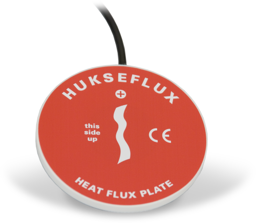
Hukseflux 社製の HFP01 は、通常、エネルギーバランスまたはボーエン比フラックスシステム用の土壌熱流束を測定します。周囲の媒体の熱流束に比例する電圧信号を出力します。空間平均化を行うには、サイトごとに少なくとも 2 つのセンサが必要です。異質な媒体があるサイトでは、追加のセンサが必要になる場合があります。
続きを読む利点と特徴
- ほとんどのCampbell Scientificデータロガーに対応
- CWS900シリーズインターフェースと互換性があり、ワイヤレスセンサネットワークで使用可能
イメージ


詳細
注意: エネルギーバランス設置では、穴を埋め戻す前にすべてのセンサを土壌面に完全に挿入する必要があります。
仕様
| センサタイプ | サーモパイル |
| 感度 | 50 μV W-1 m-2 (名目) |
| 公称抵抗 | 2 Ω |
| 温度範囲 | -30° ~ +70°C |
| センサー熱抵抗 | < 6.25 x 10⁻³ K m2 W-1 |
| 測定範囲 | ±2000 W m-2 |
| 予想される標準精度 | 一般的な土壌で -15% ~ +5% 以内 (合計12時間) |
| プレート直径 | 80 mm (3.15 in.) |
| プレート厚さ | 5 mm (0.20 in.) |
| 重量 | 200 g (7.05 oz) ケーブル除く |
ドキュメント
よくある質問
HFP01-Lに関するよくある質問の数: 10
すべて展開すべて折りたたむ
-
これは、壁を通る熱流束を表すために使用される符号規則によって異なります。HFP01-L の赤い面から入り、青い面から出る熱流束は、正のアナログ出力または正の熱になります。プレートがすでに取り付けられていて、反対の符号規則を使用することが望ましい場合は、乗数の符号を変更して負の値にします。
-
はい、ただし、接着性裏地付きのヒートシュリンクを使用して接合部を覆うなど、接合部が防水になるように注意する必要があります。ケーブルを接合すると、ケーブルに水が入り込み、ショート、腐食、その他の潜在的な問題が発生する可能性が高くなり、測定の問題が発生する可能性があります。
潜在的な問題があるため、センサケーブルを接合する前に、まずCampbell Scientificに連絡してセンサについて詳細にご相談ください。
-
キャリブレーション シートに含まれる情報は、センサごとに異なります。一部のセンサでは、シートにデータロガーをプログラムするために必要な係数が含まれています。その他のセンサでは、キャリブレーション シートは合格/不合格レポートです。
-
すべてのセンサに異なるケーブル終端オプションがあるわけではありません。特定のセンサで利用可能なオプションは、センサ製品ページの注文情報エリアの 2 つの場所で確認できます。
モデル番号
ケーブル終端オプション リスト
センサが –ET、–ETM、–LC、–LQ、または –QD バージョンで提供されている場合、そのオプションが利用可能かどうかはセンサモデル番号に反映されます。たとえば、034B は 034B-ET、034B-ETM、034B-LC、034B-LQ、および 034B-QD として提供されています。その他のすべてのケーブル終端オプション (利用可能な場合) は、センサ製品ページの注文情報エリアの「ケーブル終端オプション」の下にリストされています。たとえば、034B-L 風力発電セットは、034B-L 製品ページの注文情報エリアに示されているように、–CWS、–PT、および –PW オプションで提供されています。
注意: 新しい製品が在庫に追加されると、通常は複数のモデル番号を作成するのではなく、1 つのセンサモデルの下に複数のケーブル終端オプションをリストします。たとえば、HC2S3-L には、HC2S3-LC モデルではなく、CS110 に接続するための –C ケーブル終端オプションがあります。
-
Campbell Scientific のセンサのほとんどは、ユーザー指定のケーブル長を示す –L として提供されています。センサが –LX モデル (「X」は他の文字) としてリストされている場合、そのセンサのケーブルの長さはユーザー指定ですが、固有のシステム用の特定のコネクタで終端されます。
- -LC モデルには、ET107、CS110、または廃止された Metdata1 に接続するためのユーザー指定のケーブル長があります。
- -LQ モデルには、RAWS-P 気象ステーションに接続するためのユーザー指定のケーブル長さがあります。
センサのメイン モデル番号の後に –L または –LX の指定がない場合、センサのケーブル長は設定されています。ケーブル長は、製品の注文情報の説明フィールドの末尾に記載されています。たとえば、034B-ET モデルの説明は、「ET ステーション用 Met One Wind セット、67 インチ ケーブル」です。ケーブル長が設定されている製品は、デフォルトでバラ線で終端されます。
ケーブルが特定のシステム用の特別なコネクタで終端されている場合、モデル番号の末尾でそのシステムを指定します。たとえば、034B-ET モデルは、ET107 システムのセンサを 034B として指定します。
- –ET モデルは、ET107 気象ステーション用のコネクタです。
- –ETM モデルは ET107 気象ステーション用のコネクタですが、交換部品を購入するときに便利な特別なシステム マウントも含まれています。
- –QD モデルは、RAWS-F クイック展開ステーション用のコネクタです。
- –PW モデルは、PWENC または配線済みシステム用のコネクタです。
-
HFP01-L は、サーモパイルを使用してプレート全体のフラックスを測定します。サーモパイルの出力は、サーモパイル全体の温度勾配に比例します。HFP01-L の公称較正は 20 W m-2 /mV です。HFP01-L の出力電圧は、プレート全体の温度勾配 (フラックス) によって異なります。
-
これは、キャリブレーション シートに含まれる情報によって異なります。
- キャリブレーション シートに係数情報が含まれている場合、Campbell Scientific はコピーを保管し、交換コピーを要求することができます。
- キャリブレーション シートに係数が含まれていない場合、Campbell Scientific はコピーを保管しません。製造元に連絡して交換用コピーを入手できる場合があります。
-
多くの Campbell Scientific センサは、さまざまなケーブル終端オプションで利用できます。これらのオプションには次のものがあります。
- –PT (–PT w/Tinned Wires) オプションはデフォルトのオプションであり、他のオプションのように製品ラインには表示されません。ケーブルは、データロガーに直接接続するバラ線で終端します。
- –C (–C w/ET/CS110 コネクタ) オプションでは、ケーブルは CS110 電界メータまたは ET シリーズ気象ステーションに接続するコネクタで終端します。
- –CWS (–CWS w/CWS900 コネクタ) オプションでは、ケーブルは CWS900 シリーズ インターフェイスに接続するコネクタで終端します。CWS900 シリーズ インターフェイスに接続すると、センサをワイヤレス センサー ネットワークで使用できるようになります。
- –PW (–PW w/Pre-Wire Connector) オプションでは、ケーブルは事前に配線されたエンクロージャに接続されるコネクタで終端します。
- –RQ (–RQ w/RAWS コネクタ) オプションでは、ケーブルは RAWS-P 常設リモート自動気象ステーションに接続するコネクタで終端します。
注意: ケーブル終端オプションの選択肢はセンサによって異なります。たとえば、センサには選択可能なオプションがまったくないか、複数ある場合があります。特定のセンサに必要なオプションがリストされていない場合は、Campbell Scientific に問い合わせてサポートを受けてください。
-
IR 放射の損失のため、ほぼすべてのサーモパイル計器には通常、負のオフセットがあります。このオフセットは夜間に最も目立ち、ゼロではなく小さな負の値が読み取られます。この同じオフセットは日中にも存在しますが、太陽信号が大きいため目立ちません。
もう 1 つの一般的な問題は、計器の水平調整です。サーモパイル計器の水平調整では、コサイン応答が正しくないため、直接ビーム成分にエラーが発生する可能性があります。太陽が地平線に近い場合、角度が非常に浅いため、これらのエラーはより顕著になります。
-
ワイヤレス センサ インターフェイスと互換性のあるセンサをワイヤレス ネットワークに組み込むには、CWS900 シリーズ ワイヤレス センサ インターフェイスと、それを構成するための A205 CWS-PC インターフェイスが必要です。
ケーススタディ
ユタ州地質調査所は、ユタ州水利権局の支援を受けて、ユタ州全域に蒸発散量を測定するための渦相関観測所のネットワークを構築しました。これらの観測所は、陸地からの水の蒸発と植物による水の蒸散を合わせた量を測定します。消費的使用、つまり植物によって吸収され蒸散される水は、耕作地を含む植生地帯の蒸発散に大きく貢献します。 ユタ州の水管理者が農業活動によって節約または使用される水を正確に判断するには、同州における水使用の地上測定の改善が不可欠です。ユタ フラックス ネットワーク (UFN) の目的は 2 つあります。1 つは、渦共分散法を使用してフィールドでの蒸発散量を測定し、そのデータを衛星で収集した測定値と比較することです。この目的のため、UFN はこれまでに 4 つの渦共分散ステーションを設置しており、今後もさらに設置する予定です。 これらのステーションは、研究グレードの計測機器のコア セットから構築されています。各ステーションには次のものが含まれます。 データロガー(CR1000XまたはCR6) 統合型音波風速計付きガス分析装置 (IRGASON) 温度および相対湿度プローブ(EE181-L) 4ウェイネットラジオメーター(NR01-L) 土壌熱流計(HFP01-L) 土壌温度センサー(TCAV-L) 土壌水分センサー(CS655およびSoilVue™10) 機械式風速計と風向計 光合成有効放射線(PAR)センサー 太陽光発電システム 各観測所は、観測所の風上地域に出入りする水蒸気、CO2、エネルギーの動きを正確に測定します。純放射計と土壌センサーは、エネルギーバランスと土壌熱流束を研究するために使用されます。これらの機器はすべて非常に正確で、その多くは極めて高い速度で測定値を取得できます。 ユタ州サンファン郡の......続きを読む
持続可能なイノベーションのための国際パートナーシップ 農業における水利用の改善は、気候変動にうまく適応するために不可欠です。FarmImpact プロジェクトでは、ドイツと南アフリカのパートナーが技術的ソリューションと生態学的アプローチを組み合わせて、南アフリカの西ケープ州におけるワインや果物の栽培の微気候と生産性に対する防風垣の影響を調査します。 南アフリカは、今後数十年で気候変動とそれが農業、ブドウ栽培、果樹栽培に及ぼす悪影響に関して、より大きな課題に直面することになります。アグロフォレストリーシステムは、農業の気候変動への適応に貢献することができます。研究プロジェクト「南アフリカのアグロフォレストリー - 変動する気候下での革新的な土地利用システムの新しい道筋」(ASAP) は、気候変動の影響への適切な対応として、農業地帯に樹木を植えることを目指しています。このプロジェクトは、ドイツ、ナミビア、南アフリカの研究機関と大学間の共同研究プロジェクトを確立するための研究プログラム「SPACES II - 南アフリカの複雑な地球システムプロセスへの適応のための科学パートナーシップ」に貢献しています。このプログラムは、地球システム管理に関する科学的推奨事項の策定に貢献し、この地域の複数の生態系サービスの持続可能な利用を確保することを目的としています。SPACES II は、ドイツ教育研究省 (BMBF) の資金提供を受けています。 農業用水の利用の調査 水不足は、気候変動の影響、人間の脆弱性、生物多様性と生態系機能の喪失とともに、南アフリカにおける最大の課題の 1 つです。特に農業は、顕著な乾期と水不足によって脅かされています。小麦、ワイン、果物の栽培の中心地である西ケープ州は、国の食糧安全保障にとって非常に重要です。これに加えて、南アフリカは長年にわたり、ヨーロッパへの農林産物の主要輸出国となっています。 ドイツ、コットブスのブランデンブルクエネルギー技術センター(CEBra)のマイク・ヴェステ博士とドイツ、ミュンヘベルクのライプニッツ農業景観研究センター(ZALF)のロジャー・ファンク博士は、南アフリカのステレンボッシュ大学植物学・動物学部のケリー・アン・グレイとガイ・ミッドグレイと共同で、ステレンボッシュ地域の柑橘類の果樹園とブドウ園における樹木と作物の相互作用を調査しています。その目的は、発見された環境上の利点を利用して、農業景観に統合する必要がある革新的で多目的な土地利用管理方法としてのアグロフォレストリーシステムの利用を支援することです。したがって、典型的なアグロフォレストリーシステムを体系的に調査し、隣接する一年生作物と永年作物の放射と熱収支に対する樹木の影響を判断します。この文脈では、個々の樹木、防風林、または小規模の森林でさえも、周囲の地表温度に好ましい影響を及ぼし、それが隣接する作物の熱とエネルギーのバランスに特に良い影響を与えます。この目的のために、Apogee Instruments......続きを読む
Privacy Policy Update
We've updated our privacy policy. 詳細はこちら
Cookie Consent
Update your cookie preferences. クッキーの設定を更新する


