セルフキャリブレーション: エネルギーバランスとボーエン比システムに最適


概要
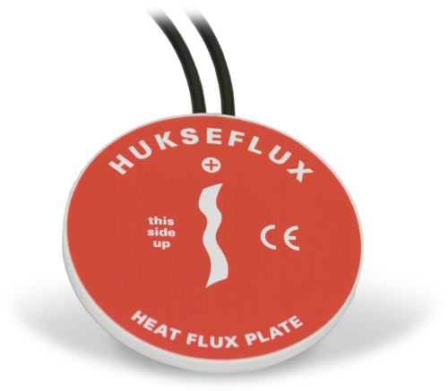
Hukseflux 社製の HFP01SC は、通常、エネルギーバランスまたはボーエン比フラックスシステム用の土壌熱流束を測定します。この製品は、可能な限り最高の測定精度を必要とするアプリケーション向けです。周囲の媒体の熱流束に比例する電圧信号を出力します。空間平均化を行うには、サイトごとに少なくとも 2 つのセンサが必要です。異質な媒体があるサイトでは、追加のセンサが必要になる場合があります。
続きを読む利点と特徴
- センサと周囲の媒体の熱伝導率の違い、温度変化、わずかなセンサの不安定性による誤差を補正
- ほとんどのCampbell Scientificデータロガーと互換性あり
- Van den Bos-Hoeksma自己校正方式を採用し、高い測定精度を実現
イメージ


詳細
注意: エネルギーバランスの設置では、穴を埋め戻す前に、すべてのセンサを土壌面に完全に挿入する必要があります。
仕様
| センサタイプ | フィルムヒーター付きサーモパイル |
| 感度 | 50 μV W-1 m-2 (名目) |
| 公称抵抗 | 2 Ω |
| 温度範囲 | -30° ~ +70°C |
| 予想される標準精度 | 読み取り値の±3% |
| ヒーター抵抗 | 100 Ω (名目) |
| ヒーター電圧入力 | 9 ~ 15 Vdc |
| ヒーター電圧出力 | 0 ~ 2 Vdc |
| 校正時間 | 1.5 W で±3 分 (通常3~6時間ごとに実施) |
| 平均消費電力 | 0.02 ~ 0.04 W |
| プレート直径 | 80 mm (3.15 in.) |
| プレート厚さ | 5 mm (0.20 in.) |
| 重量 | 200 g (7.05 oz) ケーブル除く |
ダウンロード
CR1000X HFP01SC Example program v.2 (3 kb) 18-02-2020
CR1000X program that measures the HFP01SC, performs the self-calibration, and checks for calibration validity. Refer to the manual for the equations used for the self-calibration and calibration-validity checks. A table in the manual provides a cross reference of the terms in the equations in the manual with the constants and variables in the example data logger program.
よくある質問
HFP01SC-Lに関するよくある質問の数: 13
すべて展開すべて折りたたむ
-
いいえ。HFP01SC-L は媒体と完全に接触している必要があります。鉄道のバラストは粗すぎます。
-
キャリブレーション中にミリボルト出力を見つけるために実行平均を使用するのではなく、50 Hz または 60 Hz の積分で単一のサンプルを使用します。HFP01SC-L マニュアルの 2014 以降のバージョンの例 1 を参照してください。
-
サンプルの CRBasic プログラムは、SequentialMode または PipeLineMode のいずれかで実行されます。CRBasic プログラムを PipeLineMode で強制的に実行するには、プログラムの先頭に PipeLineMode 命令を追加します。
-
キャリブレーション サイクル中に HFP01SC-L が土壌と完全に接触していない場合、キャリブレーション シフトが発生します。土壌の凍結/融解サイクル、極端な乾燥/湿潤サイクルによる土壌の膨張/収縮、またはプレートを通り抜けるげっ歯類などにより、プレートが土壌と接触しなくなる可能性があります。
-
現場校正は、品質保証/品質管理に役立ちます。現場校正で決定された乗数は、工場で決定された校正の ±10% 以内である必要があります。そうでない場合は、プレートが損傷しているか、データロガーに正しく配線されていないか、土壌と完全に接触していない可能性があります。
-
キャリブレーション シートに含まれる情報は、センサごとに異なります。一部のセンサでは、シートにデータロガーをプログラムするために必要な係数が含まれています。その他のセンサでは、キャリブレーション シートは合格/不合格レポートです。
-
すべてのセンサに異なるケーブル終端オプションがあるわけではありません。特定のセンサで利用可能なオプションは、センサ製品ページの注文情報エリアの 2 つの場所で確認できます。
モデル番号
ケーブル終端オプション リスト
センサが –ET、–ETM、–LC、–LQ、または –QD バージョンで提供されている場合、そのオプションが利用可能かどうかはセンサモデル番号に反映されます。たとえば、034B は 034B-ET、034B-ETM、034B-LC、034B-LQ、および 034B-QD として提供されています。その他のすべてのケーブル終端オプション (利用可能な場合) は、センサ製品ページの注文情報エリアの「ケーブル終端オプション」の下にリストされています。たとえば、034B-L 風力発電セットは、034B-L 製品ページの注文情報エリアに示されているように、–CWS、–PT、および –PW オプションで提供されています。
注意: 新しい製品が在庫に追加されると、通常は複数のモデル番号を作成するのではなく、1 つのセンサモデルの下に複数のケーブル終端オプションをリストします。たとえば、HC2S3-L には、HC2S3-LC モデルではなく、CS110 に接続するための –C ケーブル終端オプションがあります。
-
Campbell Scientific のセンサのほとんどは、ユーザー指定のケーブル長を示す –L として提供されています。センサが –LX モデル (「X」は他の文字) としてリストされている場合、そのセンサのケーブルの長さはユーザー指定ですが、固有のシステム用の特定のコネクタで終端されます。
- -LC モデルには、ET107、CS110、または廃止された Metdata1 に接続するためのユーザー指定のケーブル長があります。
- -LQ モデルには、RAWS-P 気象ステーションに接続するためのユーザー指定のケーブル長さがあります。
センサのメイン モデル番号の後に –L または –LX の指定がない場合、センサのケーブル長は設定されています。ケーブル長は、製品の注文情報の説明フィールドの末尾に記載されています。たとえば、034B-ET モデルの説明は、「ET ステーション用 Met One Wind セット、67 インチ ケーブル」です。ケーブル長が設定されている製品は、デフォルトでバラ線で終端されます。
ケーブルが特定のシステム用の特別なコネクタで終端されている場合、モデル番号の末尾でそのシステムを指定します。たとえば、034B-ET モデルは、ET107 システムのセンサを 034B として指定します。
- –ET モデルは、ET107 気象ステーション用のコネクタです。
- –ETM モデルは ET107 気象ステーション用のコネクタですが、交換部品を購入するときに便利な特別なシステム マウントも含まれています。
- –QD モデルは、RAWS-F クイック展開ステーション用のコネクタです。
- –PW モデルは、PWENC または配線済みシステム用のコネクタです。
-
これは、キャリブレーション シートに含まれる情報によって異なります。
- キャリブレーション シートに係数情報が含まれている場合、Campbell Scientific はコピーを保管し、交換コピーを要求することができます。
- キャリブレーション シートに係数が含まれていない場合、Campbell Scientific はコピーを保管しません。製造元に連絡して交換用コピーを入手できる場合があります。
ケーススタディ
概要 気候変動との戦いにおいて、大気中の温室効果ガス濃度の上昇という地球規模の課題に対処するための革新的な解決策が生まれています。英国生態学・水文学センター (UKCEH) は、アベリストウィス大学などと提携して、この研究の最前線に立っています。Campbell Scientific社の最先端の渦相関システムを使用して、UKCEH はさまざまな作物による CO2 吸収を監視するプロジェクトを先導しており、主に多用途のススキ (エレファント グラス) に焦点を当てています。 課題 大気中の温室効果ガス濃度の上昇という差し迫った問題に対処するには、その地球温暖化への影響を総合的に理解し、その影響を緩和する必要があります。課題は、エネルギー安全保障と農村経済を維持しながら、大気中の CO2 濃度の削減に積極的に貢献する持続可能な解決策を見つけることです。 解決策 UKCEH は、キャンベル サイエンティフィック社の高度な渦相関システムを導入し、作物による大気中の CO2......続きを読む
このケーススタディでは、中国科学院清遠森林 CERN 研究所の不均一な地形におけるCO 2 /H 2O微量ガスフラックスを測定する理論と技術を探すためにCPEC310およびAP200システムを統合する方法について説明します。 CPEC310 (閉路渦相関システム) と AP200 (大気プロファイル システム) は、微気象センサー、硝酸塩関連の微量ガス分析装置、土壌表面 CO 2フラックス システムとともに、中国科学院清遠森林 CERN フィールド研究所における森林生態学と管理に関する研究を促進する 3 つの高さ......続きを読む
科学者や土地利用管理者は、炭素吸収における森林地帯の重要性を長い間認識してきました。研究と国際政策は主に熱帯林と生息地に焦点が当てられてきました。熱帯林と生息地は成長が早く、頻繁な伐採の影響を受けやすいためです。しかし最近では、安定的に炭素を吸収して貯蔵できる生息地が地球全体の炭素状況の重要な部分であると認識されるようになり、寒帯地域などの冷涼な気候の景観に研究の焦点が当てられるようになりました。これらの地域では成熟した森林と気温によって分解速度が制限されるため、気候変動がこれらの景観を変える潜在的な影響により、景観をより完全に理解するための取り組みが強化されています。 アラスカ大学フェアバンクス校の研究者らは、米国地質調査所の資金援助を受け、国立科学財団の長期生態学研究ネットワークの一部であるボナンザ クリーク実験林内の 3 か所の環境モニタリング サイトに機器を設置しました。これらのサイトは、微気候の違いによって決まる陸上北方景観の重要な生息地を代表する永久凍土の劣化の年代順に位置しています。3 つのサイトには、クロトウヒ林 (クロトウヒの森がそのまま残っている安定した永久凍土の地域)、永久凍土が下にある地表の氷が溶けて樹木がかなり枯死している活発なサーモカルスト サイト、活動層の深さが深く安定した樹木のない湿原サイトが含まれます。 このプロジェクトの目標は、北極圏の気候システムにおける地表、大気、海洋間の重要なつながりとフィードバックである炭素、水、エネルギーのフラックスを年間を通じて継続的に測定することです。これまで、北極圏では環境条件が厳しく、遠隔地へのアクセスが困難なため、このような研究はほとんど行われていません。冬季に太陽光発電が限られ、風力発電が実行可能な選択肢ではない場所で継続的に監視するには、電力要件が極めて低く、リモート システム診断機能を備えた堅牢なセンサーを選択する必要があります。 Bonanza Creek サイトで、渦相関フラックス測定に Campbell Scientific の EC150......続きを読む
オースティン カレッジ気象ステーション (ACWX) は、シャーマンの西約 10 マイルにあるオースティン カレッジのスニード環境研究エリアにあります。この気象ステーションは、北テキサスの天気と気候を研究するユニークな機会を提供します。 2001 年春に物理学の学部生によって設立されたこの気象観測所の主な目的は次のとおりです。 陸地大気研究のための表面エネルギーバランスの測定 オースティン大学と地域社会に信頼できる気象情報を提供する 学部生を質の高い科学研究に参加させること...続きを読む
Privacy Policy Update
We've updated our privacy policy. 詳細はこちら
Cookie Consent
Update your cookie preferences. クッキーの設定を更新する


