概要
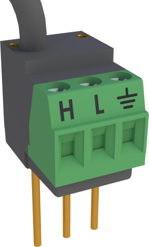
4WFBS120 は、単一の可変抵抗器として機能するひずみゲージまたはその他のセンサ用の補完抵抗器を提供する 4 線式フルブリッジ モジュールです。このモジュールは、公称抵抗が 120Ω のセンサを測定するために使用します。
続きを読む利点と特徴
- 取り付けまたは取り外しが簡単
- データロガーの入力端子に直接接続
- ほとんどの Campbell Scientific データロガーと互換性があります
イメージ

CAD ファイル:
詳細
4WFBS120 は、完全なホイートストン ブリッジを完了します。また、ダミー ゲージを使用した 1/4 ブリッジひずみ回路 (1 つのアクティブ要素) または 1/2 ブリッジひずみ回路 (2 つのアクティブ要素) で使用するために、ホイートストン ブリッジの後半部分を完了するためにも使用できます。ホイートストン ブリッジ回路は、抵抗の小さな変化を、データロガーが測定できる出力電圧に変換します。
4WFBS120 には、感度エラーの補正に使用されるシャント キャリブレーションを実行できる 2つの外部ピンが含まれています。
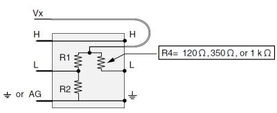
4 線式フル ブリッジ モジュールの回路図
(4WFBS120 の場合、R4 = 120 Ω)

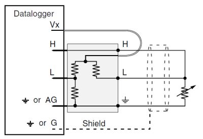
4WFBS120 とセンサの接続

仕様
| 使用例 | 4線式ひずみゲージまたは公称抵抗が120Ωのその他のフルブリッジ測定 |
| 寸法 | 1.5 x 1.5 x 2.7 cm (0.6 x 0.6 x 1.0 in.) プロング付き本体 |
| 重量 | 6 g (0.2 oz) |
2:1 抵抗分配器 |
|
| 抵抗 | 1 kΩ/1 kΩ |
| 許容範囲 | 比率: ±0.01% (@ 25°C) |
| 最大温度係数 | 比率: 0.5 ppm/°C (-55° ~ +85°C) |
| 出力定格 | 0.1 W (@ 70°C) /要素 |
完成抵抗器(バルク金属箔) |
|
| 抵抗 | 120 Ω |
| 許容範囲 | ±0.01% (@ 25°C) |
| 最大温度係数 | 0.8 ppm/°C |
| 出力定格 | 0.25 W (@ 70°C) |
互換性
注意: 以下は代表的な互換性情報を示しています。互換性のある製品や互換性のない製品をすべて網羅したリストではありません。
Data Loggers
| 製品 | 互換性 | 注意 |
|---|---|---|
| 21X (リタイア) | ||
| CR10 (リタイア) | ||
| CR1000 (リタイア) | ||
| CR10X (リタイア) | ||
| CR200X (リタイア) | ||
| CR206X (リタイア) | ||
| CR211X (リタイア) | ||
| CR216X (リタイア) | ||
| CR23X (リタイア) | ||
| CR295X (リタイア) | ||
| CR300 (リタイア) | ||
| CR3000 (リタイア) | ||
| CR310 | ||
| CR350 | ||
| CR500 (リタイア) | ||
| CR5000 (リタイア) | ||
| CR510 (リタイア) | ||
| CR6 | ||
| CR800 (リタイア) | ||
| CR850 (リタイア) |
その他
| 製品 | 互換性 | 注意 |
|---|---|---|
| CR9050 (リタイア) |
互換性に関する追加情報
マルチプレクサ
4WFBS120 は、当社のマルチプレクサと互換性があります。
データロガーの考慮事項
4WFBS120 は、1つのディファレンシャルアナログ入力を使用します。隣接するアナログ グランド チャンネルは、4WFBS120 の「接地端子」を受け入れます。すべてのデータロガー ターミナル ストリップのすべてのチャネルでこのシーケンスが採用されているわけではないため、特に複数のターミナル入力モジュールを使用する予定の場合は、データロガーの配線パネルをチェックしてチャンネルの割り当てを確認してください。
4WFBS120 のヘッドから出ているリード線は、データロガーの励起チャンネルに接続します。
同じアプリケーションで CR10X を使用して熱電対を測定する場合、新しい CR10X 配線パネルと CR10XTCR 基準サーミスタ (付属の熱電対カバー付き) は、ターミナル入力モジュールが取り付けられたデータロガーの入力チャネルをカバーするのに十分な深さがありますが、古い CR10TCR は深さが足りません。
プログラミング
4WFBS120 は、CRBasic では BrFull Instruction で、Edlog では Instruction 6 (フル ブリッジ) で測定されます。
よくある質問
4WFBS120に関するよくある質問の数: 5
すべて展開すべて折りたたむ
-
CR1000 励起チャネルの電流制限は、2500 mV で 25 mA です。複数の 4WFBS120 モジュールで 120 オームのゲージを使用する場合、2500 mV 励起の各励起チャネルに接続できるゲージは 2 つだけです。励起チャネルごとに 3 つのゲージを使用する場合は、励起を約 1750 mV に下げる必要があります。
-
ST350 は、4WFBS350 や 4WFBS120 などの補完モジュールを追加せずに、データロガー (またはデータロガーに接続されたマルチプレクサ) に直接接続できる 4 つのアクティブ要素を備えたフル ブリッジひずみトランスデューサとして設計されています。
-
各データロガーには、特定の励起電流供給機能があります。同じ励起チャンネルから複数のひずみゲージを励起しようとする場合は、下記の電流制限を超えないようにする必要があります。
- 4WFBS120 の等価抵抗は 214.285 オームです。回路が 2.5 V (2500 mV) で励起されている場合、11.67 mA (2500 mV / 214.285 オーム = 11.67 mA) が消費されます。
- 4WFBS350 の等価抵抗は 518.518 オームです。回路が 2.5 V (2500 mV) で励起されている場合、4.82 mA (2500 mV / 518.518 オーム = 4.82 mA) が消費されます。
- 4WFBS1K の等価抵抗は 1000.00 オームです。回路が 2.5 V (2500 mV) で励起されている場合、2.5 mA (2500 mV / 1000 オーム = 2.5 mA) が消費されます。
-
ブリッジ抵抗が十分に高いか、励起電圧が制限されている場合、複数のひずみゲージ センサが同じ励起チャンネルを使用できます。制限は励起端子の電流容量 (2.5 V で 25 mA) と回路の等価抵抗によって決まります。
-
ひずみゲージ測定を行うには、端子入力モジュールが必要です。ひずみゲージの抵抗と端子入力モジュールの抵抗を一致させる必要があります。
- 120 オームのひずみゲージの場合は、4WFBS120 を使用します。
- 350 オームのひずみゲージの場合は、4WFBS350 を使用します。
- 1000 オーム (1 キロオーム) のひずみゲージの場合は、4WFBS1K を使用します。
Privacy Policy Update
We've updated our privacy policy. 詳細はこちら
Cookie Consent
Update your cookie preferences. クッキーの設定を更新する


